ELFOS
Code Version 3.0

Touch one of the buttons on the screen image to get more details on what each does.

When you start the machine, the splash screen is shown as on the right. Touching one of the buttons on the top row will take you to that screen.

This is a sophisticated program, so give it a few minutes to load.

If you are new to using this machine, I recommend you start with the Main screen. You will have a lot to learn there before moving to other screens.


The version you are using shows in the lower right corner of the opening screen. "v3.0" is shown here, denoting the use of version 3.0.


The links below are intended to help the ornamental turner perform activities which are commonly performed on the MDF Rose Engine lathe. Special thanks to the Nerds of Woodworking for their help in compiling these. This list will be expanded as time permits for adding the documentation.

Index of Activities, Calculators, and Other Key Information

Calculators
F
I
N
P
S
T


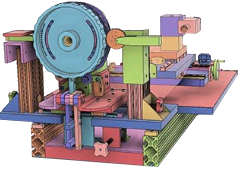
As you use the controls for operating the MDF Rose Engine Lathe, the axes referenced follow the convention as shown below.

Some have questioned this convention, in particular the Z axis being aligned the way that it is. But, whilst this may not seem to follow the Cartesian coordinates you learned in school, it actually does. This approach is based on the axes as envisioned from the object being turned, not the viewer. And, more importantly, this is an industry standard for lathe work.


Lathe Axes
Axis Comments
X Movement on this axis is horizontal movement across the end of the object being shaped on the lathe.

This movement is accomplished by use of the cross slide or other similar mechanism.
Y This axis does not typically have movement. Instead, it is typically a measurement of the vertical placement of the cutter in the quick change tool post.

Movement on this axis can happen if a straight-line chuck is used; however this is pretty advanced stuff.

Motion on the Y axis is not typically managed by the control system; however, one of the other axes could be used. For example, if a stepper motor is used on the straight-line chuck to move the object up and down, then that stepper motor could be controlled as if it were the X (or Z or B) axis. The user will just have to manage the change in their thinking as they use the control system.
Z Movement on this axis is horizontal movement along the side of the object being shaped on the lathe.

This movement is accomplished by use of the cross slide or other similar mechanism.

  • The spindle rotates about the Z axis.
  • Pumping is movement along the Z axis.
M3 M3 replaced the B axis.

M3 is not truly an axis per se. Rather, the controls provide for managing a 3rd stepper motor, and allows the user to configure the stepper motor for either of these movement types.

Movement Used for
Linear

Movement is via a linear slide, and is measured in distance (e.g., inches).

Examples include stepper motor controls driving movement on:

  • Cross Slide
  • Spherical Slide (lead-screw driven)
  • Straight-line Chuck
Rotational

Movement is via rotational movement, and is measured in degrees of rotation.

Examples include stepper motor controls driving movement on:

  • Spherical Slide (gear driven)
  • Variable Rosette Phasing Drive
M4 This is also not truly an axis per se. Rather, the controls provide for managing a 4th stepper motor. This stepper moter can be configured the same as for M3.

Stepper motor movements are managed:

  • Spindle
  • X Axis
  • Z Axis
  • M3
  • M4

Limit Switches

Limit switches can be used for all screens except Index and Greek Key.

More information about the implementation of limit switches is on the limit switches config page.

Note: These pages are setup for split screen viewing to allow for keeping the program's screen image fixed whilst scrolling the textual information. Because of that, the pages don't work well on small screens like hand phones.


Questions or comments? Contact us at
ColvinTools@Gmail.com
Disclaimers