|
|
Control System for Multiple Stepper Motors |
|

|
Used to return to the prior screen. | |||||||||||||||||||||||||||||||||||||||||||||||||||||||||||||||||||||||||||||||||||||||||||||||||||||||||||||||||||||||||||||||||||||||||||||||||||||||||||||||||||||||||||||||||||||||||||||||||||||||||||||||||||||||||||||||||||||||||||||||||||||||||||||||||||||||||||||||||||||||||||||||||||||||||||||||||||||||||||||||||||||||||||||||||||||||||||||||||||||||||||||||||||||||||||||||||||||||||||||||||||||||||||||||||||||||||||||||||||||||||||||||||||||||||||||||||||||||||||||||||||||||||||||||||||||||||||||||||||||||||||||||||||||||||||||||||||||||||||||||||||||||||||||||||||||||||||||||||||||||||||||||||||||||||||||||||||||||||||||||||||||||||||||||||||||||||||||||||||||||||||||||||||||||||||||||||||||||||||||||||||||||||||||||||||||||||||||||||||||||||||||||||||||||||||||||||||||||||||||||||||||||||||||||||||||||||||||||||||||||||||||||||||||||||||||||||||||||||||||||||||||||||||||||||||||||||||||||||||||||||||||||||||||||||||||||||||||||||||||||||||||||||||||||||||||||||||||||||||||

|
Used to refresh the values shown in the gray boxes. | |||||||||||||||||||||||||||||||||||||||||||||||||||||||||||||||||||||||||||||||||||||||||||||||||||||||||||||||||||||||||||||||||||||||||||||||||||||||||||||||||||||||||||||||||||||||||||||||||||||||||||||||||||||||||||||||||||||||||||||||||||||||||||||||||||||||||||||||||||||||||||||||||||||||||||||||||||||||||||||||||||||||||||||||||||||||||||||||||||||||||||||||||||||||||||||||||||||||||||||||||||||||||||||||||||||||||||||||||||||||||||||||||||||||||||||||||||||||||||||||||||||||||||||||||||||||||||||||||||||||||||||||||||||||||||||||||||||||||||||||||||||||||||||||||||||||||||||||||||||||||||||||||||||||||||||||||||||||||||||||||||||||||||||||||||||||||||||||||||||||||||||||||||||||||||||||||||||||||||||||||||||||||||||||||||||||||||||||||||||||||||||||||||||||||||||||||||||||||||||||||||||||||||||||||||||||||||||||||||||||||||||||||||||||||||||||||||||||||||||||||||||||||||||||||||||||||||||||||||||||||||||||||||||||||||||||||||||||||||||||||||||||||||||||||||||||||||||||||||||
| Preferences Screen |
|
Touch the buttons on the screen image to the right to see the details for the that screen.
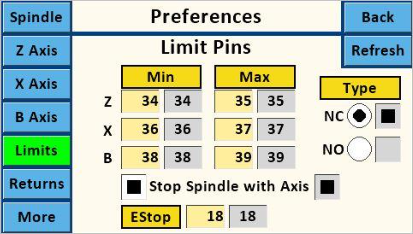
Purpose: Set (Teensy) pin numbers to be used for limit switches.
The use of a specific pin for Min or Max for any given axis is not critical. However, using the same pin # for Min and Max is not recommended. The reason is that, if the limit is tripped for one direction, movement in that direction is halted. However, movement in the other direction is not. Note though that tripping the EStop limit will halt movement in all directions. The Teensy microcontroller allows for pins 18, 19, and 25 - 39 to be used. These need to match the ones wired to your board. Recommendation:
If the limit switch is engaged when using any function, the action button for that direction's limit switch will turn red. No further action can be taken until the Stop button is touched.
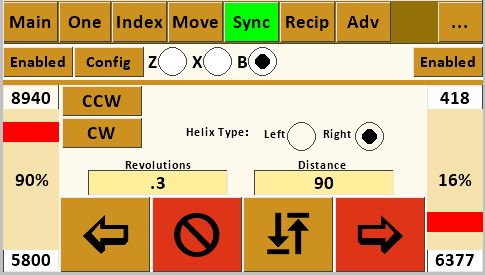
Max Limit Switch Triggered on Sync Screen
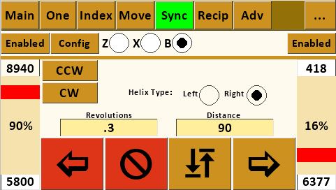
Min Limit Switch Triggered on Sync Screen 
To reset, touch the stop button. Once that is done, the opposite direction action button can be touched even though the limit switch may still be triggered. 
This is different from the limit function which performs a slow, controlled stop. The EStop is typically implemented as a big red switch like to the right.
Key Notes:
If the EStop is engaged when using any function, all the movement buttons will turn red.
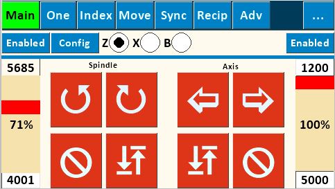
EStop on Main Screen To reset:
The EStop function was implemented with version 26.
|
| 
3.5 mm Plug Using the sleeve for the ground is key for many reasons, and that is the design outlined in Instructions for Building the Stepper Controls.
| 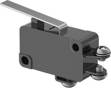
Limit Switch This can be attached to a magnetic base stand, especially one with a Noga arm, to position it where needed. We have a mounting bracket which can be 3D printed to attach this switch to the Noga arm.
| Diagnostics: If you are experiencing issues using limit switches, below are some diagnostic steps I've found useful. Limit Switches don't stop spindle movement Ensure the option on this screen, "Stop Spindle with Axis", is enabled. Recommended Action: Unless you need to not stop the spindle, leave this option checked as the default for how you use your machine. Limit Switches don't stop axis movement Ensure you have connected you limit switch to the pin configured for the respective axis. Recommended Action: If you are only going to use one limit switch, set all of these to 34, and connect your limit switch to that pin. If you are going to use two limit switches, set all the Mins to 34 and all the Maxes to 35. Stepper Motors won't run on Main or One Screens One or more limit switches may be "engaged". This can happen if they are not wired correctly or there is a short in the limit switch wiring. You can confirm that this is or is not the case by trying to drive the stepper motor motion from the screens which don't use limit switches. Recommended screen is Ind. Recommended Action: Read the instructions regarding limit switch connections in Instructions for Building the Stepper Controls. | |||||||||||||||||||||||||||||||||||||||||||||||||||||||||||||||||||||||||||||||||||||||||||||||||||||||||||||||||||||||||||||||||||||||||||||||||||||||||||||||||||||||||||||||||||||||||||||||||||||||||||||||||||||||||||||||||||||||||||||||||||||||||||||||||||||||||||||||||||||||||||||||||||||||||||||||||||||||||||||||||||||||||||||||||||||||||||||||||||||||||||||||||||||||||||||||||||||||||||||||||||||||||||||||||||||||||||||||||||||||||||||||||||||||||||||||||||||||||||||||||||||||||||||||||||||||||||||||||||||||||||||||||||||||||||||||||||||||||||||||||||||||||||||||||||||||||||||||||||||||||||||||||||||||||||||||||||||||||||||||||||||||||||||||||||||||||||||||||||||||||||||||||||||||||||||||||||||||||||||||||||||||||||||||||||||||||||||||||||||||||||||||||||||||||||||||||||||||||||||||||||||||||||||||||||||||||||||||||||||||||||||||||||||||||||||||||||||||||||||||||||||||||||||||||||||||||||||||||||||||||||||||||||||||||||||||||||||||||||||||||||||||||||||||||||||||||||||||||||


 Stop Spindle with Axis
 = Stop motion on the axis only when the limit is triggered (the spindle remains turning).
 NC = normally closed (NC) / momentary open switch
 NO = normally open (NO) / momentary close switch