Control System for Multiple Stepper Motors

Fluting


Cutting flutes along the spindle's length (the Z axis) can be achieved a number of ways, depending on the desired outcome.

Example Option Screen Used Recommended Actions
  1. Continuous Flutes using a Profiled Cutter
Ind

Main
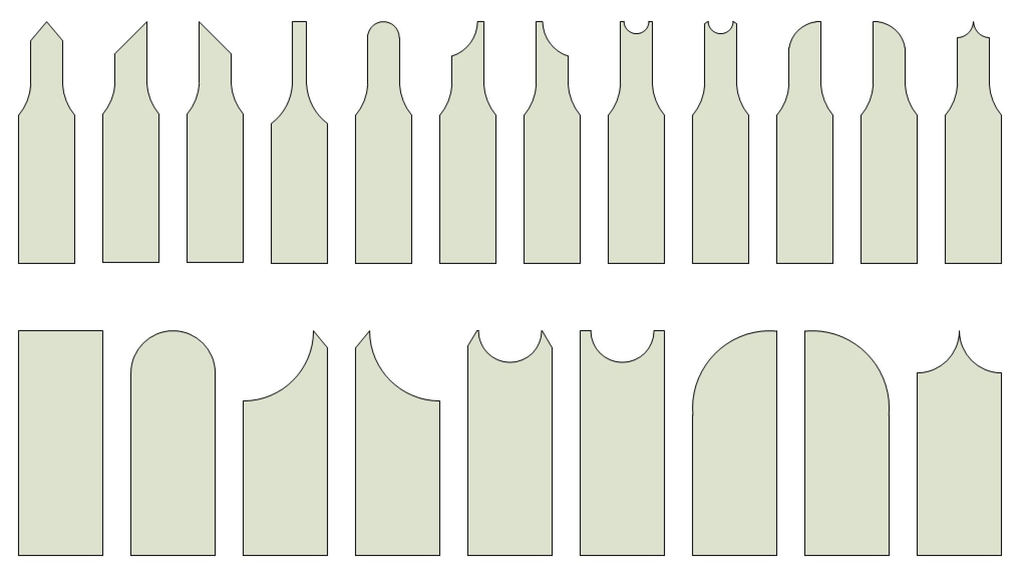
Traditional Fly Cutters

The idea behind this approach is you are cutting one flute down the entire length of the Z axis. A shaped cutter which is moved along the Z axis to cut one flute, the spindle is indexed, and the whole process is repeated until all the flutes are cut.

  • Use a cutter with a profiled shape which will yield the desired cut. Hold it in a cutting frame, and move it down the whole length.

    Some traditional cutter shapes are shown to the right. Traditionally, these fly cutters were flat pieces of metal with various shapes, and there are some ornamental turners who use these still today.

    Chris Ploof makes new cutters which have round shanks, and can fit into a cutting frame which holds such cutters. These cutting frames are significantly easier to make than the original ones made by Holtzapffel and others.

  • No rosette is used for this approach. The shape comes from the cutter's profile.

  • The headstock is held fixed (the centering block is inserted in the back, and the fading wedge dropped down).

  • The cutting frame selected and the angle of cutting can have great effects on the results achieved.

  • The shape of the rubber has no effect as no rosette is used for this.

  • The cutting frame is moved slowly down the Z axis and the spindle is not rotated during this movement. Movement of the cutter along the Z axis can be achieved at least two ways.

    • The most efficient way is to use a slide rest which has automated movement using a lead screw (e.g., a curvilinear slide). This also has the most likelihood of achieving a smooth, even finish.

    • If you don't have a slide rest which can automate the movement using a lead screw, then you will have to move it manually a small increment after each revolution. Something like 0.005" at a time is not uncommon.

Detailed Instructions for using the Control System for Multiple Stepper Motors.

  1. Continuous Flutes using a Rosette
Main

The idea behind this approach is you are cutting the rosette's design around the object, whilst also moving very slowly along the Z axis. A standard cutter is used to to cut the rosette's profile.

  • Use a rosette with the desired shape (e.g., a Holtzapffel D-12 rosette, used from the far side).

  • The angle used for the cutting frame will have different effects on the results achieved.

  • The shape of the rubber used can also have a great effect on the resulting cuts.

  • Movement of the cutter along the Z axis can be achieved at least two ways.

    • The most efficient way is to use a slide rest which has automated movement using a lead screw (e.g., a curvilinear slide). This also has the most likelihood of achieving a smooth, even finish.

    • If you don't have a slide rest which can automate the movement using a lead screw, then you will have to move it manually a small increment after each revolution. Something like 0.005" at a time is not uncommon.

Detailed Instructions for using the Nextion Multiple Stepper Control system.

  1. Helical Flutes using a Profiled Cutter
Sync

Ind

The idea behind this approach is like #1 above. The only difference is that with this one, the spindle is rotated in coordination with the movement along the Z-axis.

Detailed Instructions for using the Nextion Multiple Stepper Control system.

  1. Complex Shaped Flutes using a Rosette
Main

The idea behind this approach is also like #2 above. The difference here is that this one there is a curvilinear pattern also used to provide additional shape on the X axis.