

|
|
Control System for Multiple Stepper Motors |
|
The controls on the left and right side of the screen are for controlling the respective stepper motor's speed and acceleration.
To change the Max Speed, touch the number at the top of the slider bar, and you will be presented with the Number Pad Screen.
The slider is a red bar that can be moved up to increase the speed, or down to decrease it. The percentage shown in the bar (15% on the left, 77% on the right) shows the percentage of the Max Speed at which the stepper motor is set to run.
There is a slider for the stepper motor on each axis, and they operate independently.
The top number is the max speed for the respective axis' stepper motor. This is measured in pulses / second.
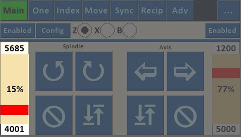
The left side controls the spindle speed. The stepper motor drivers in the MDF Rose Engine 2.0 are set to 6,400 pulses / revolution. Also, there is a 9:1 ration between the motor gear and the spindle gear, so a max speed of 5,685 would equate to: \[ \begin{align} MaxSpindleRPM & = \frac{5,685 \, \frac{\mathrm{pulses}}{\mathrm{sec}} \times \, 60 \, \frac{\mathrm{sec}}{\mathrm{min}}} {6,400 \, \frac{\mathrm{pulses}}{\mathrm{rev}} \times \, 9 \, \frac{\mathrm{motor \, revs}}{\mathrm{spindle \, revs}}} \\ & = 5.9 \, \mathrm{RPM} \end{align} \]
Thusly, at 15%,the spindle's speed is \[ \begin{align} ActualSpindleRPM & = MaxSpindleRPM \times \, 0.15 \\ & = 0.9 \, \mathrm{RPM} \\ & = 66.7 \, \frac{\mathrm{seconds}}{\mathrm{revolution}} \end{align} \]
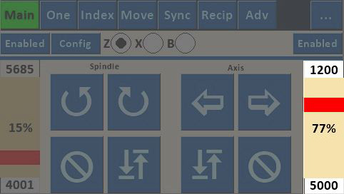
The other stepper motor (in this case, on the Z axis) directly drives the motion: there is no belt between the stepper motor and the driven element. Thusly, a max speed of 1200 would equate to: \[ \begin{align} MaxRPM & = \frac{1,200 \, \frac{\mathrm{pulses}}{\mathrm{sec}} \times \, 60 \, \frac{\mathrm{sec}}{\mathrm{min}}} {6,400 \, \frac{\mathrm{pulses}}{\mathrm{rev}}} \\ & = 11.3 \, \mathrm{RPM} \end{align} \]
Thusly, at 77%,the motor's speed is \[ \begin{align} RPM & = MaxRPM \times \, 0.77 \\ & = 8.7 \, \mathrm{RPM} \end{align} \]
Now we need to add Distance/360 to the calculate how far each revolution moves the cutter. Distance/360 is set in the Preferences Screen for the respective axis, and can be calculated easily using the applet at the bottom of that page. Or, you can calculate it yourself: \[ \begin{align} Distance/360 & = ScrewPitch \times \, ScrewStarts \\ \\ Movement Speed & = RPM \times \, Distance/360 \end{align} \]
|
This lead screw has a pitch of 2mm and 4 starts, thusly it will move 8mm per revolution. \[ \begin{align} Distance/360 & = 2 \, mm \times \, 4 \\ & = 8 \, mm \\ & = 0.31496 \, inches \end{align} \] At a speed of 8.7 RPM, this is \[ \begin{align} Movement Speed & = 8.7 \frac{\mathrm{rev}}{\mathrm{min}} \times \, 8 \frac{\mathrm{mm}}{\mathrm{rev}} \\ & = 69.6 \, \frac{\mathrm{mm}}{\mathrm{min}} \\ Movement Speed & = 8.7 \frac{\mathrm{rev}}{\mathrm{min}} \times \, 0.31496 \frac{\mathrm{inches}}{\mathrm{rev}} \\ & = 2.7 \, \frac{\mathrm{inches}}{\mathrm{min}} \end{align} \] |
This lead screw has a pitch of 5mm with 1 start (and a diameter of 16mm), thusly it will move 5mm per revolution. \[ \begin{align} Distance/360 & = 5 \, mm \times \, 1 \\ & = 5 \, mm \\ & = 0.19685 \, inches \end{align} \] At a speed of 8.7 RPM, this is \[ \begin{align} Movement Speed & = 8.7 \frac{\mathrm{rev}}{\mathrm{min}} \times \, 5 \frac{\mathrm{mm}}{\mathrm{rev}} \\ & = 43.5 \, \frac{\mathrm{mm}}{\mathrm{min}} \\ Movement Speed & = 8.7 \frac{\mathrm{rev}}{\mathrm{min}} \times \, 0.19685 \frac{\mathrm{inches}}{\mathrm{rev}} \\ & = 1.7 \, \frac{\mathrm{inches}}{\mathrm{min}} \end{align} \] |
The bottom number (4001 on the left; 5000 on the right) is the acceleration for the stepper motor. To change this value, touch the number, and you will be presented with the Number Pad Screen.
|
Questions or comments? Contact us at
ColvinTools@Gmail.com |
Disclaimers |