Used to refresh the values shown in the gray boxes.
Preferences Screen
Touch the buttons on the screen image to the right to see the details for the that screen.
Purpose: The factors on these screens control how speeds and distances are determined.
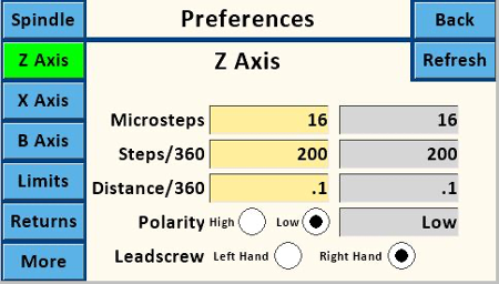
The values shown in a tan box show values on the Nextion. Touching one of the text boxes allows you to edit that value using the Number Pad screen.
The values shown in a gray box show the ones stored on the Teensy controller. These are read only and should match the settings on the Nextion.
Microsteps
This must use valid values for the stepper driver, and is usually 1, 2, 4, 16, 32, 64, or 128. These settings must match the jumper settings on the PCB.
32 is the designed value for the MDF Rose Engine Lathe 2.0.
Steps/360
This must use valid values for the stepper motor. The typical step angle is 1.8°, so this would be
\[
\frac{360 °}{1.8 °} = 200
\]
200 is the designed value for the MDF Rose Engine Lathe 2.0.
Distance/360
This is the distance the carriage moves in one revolution of its stepper motor. It is a value which can arrived at two ways:
Empirically by measuring the movement along the selected axis while the stepper motor revolves a set number of turns. This can be accomplished by entering a value in Distance/360 such as 1, then using the Move Screen to move a Distance of 20 while measuring. This should turn the motor through 20 full revolutions. Divide the distance traveled by 20 and enter calculated value into Distance/360. If the total distance moved in 20 revolutions is insignificant, use a larger Distance number like 50 (or even 100).
Note that best practice is to remove backlash from the axis' mechanism prior to the measurement run by moving the axis in the same direction. It may be possible to get a starting point for Distance/360 by calculation calculating the stepper pulley to driven pulley ratio, and/or the thread pitch.
Alternatively, it can be calculated using the lead screw's information (if known). If you built your cross slide using a lead screw with metric threads (e.g., as is typically used for 3D printers), common values are 2 mm pitch and 4 starts. The calculator below can make the Distance/360 calculation easier.
Finally, it is important to note that if you use different apparatuses (such as a cross-slide, or a spherical or a curvilinear apparatus) with this axis, each will likely have a different value for Distance/360. It is a good idea to label each apparatus.
An example is below:
Distance/360
0.31496" / 8mm
Polarity
The Polarity High and Low radio buttons for both Spindle and Z Axis are set as:
High
High setting is for use with some external stepper drivers
Low
Low is the default, which is the correct setting when using the StepperOnline DM542T and the Pololu DRV8825 Stepper Drivers.
Leadscrew
Leadscrew should be set to the thread direction of the axis leadscrew.
Left Hand
Use when using an apparatus with a left-handed threaded rod. A Hardinge compound slide-rest has a left-hand thread.
Right Hand
Use when using an apparatus with a right-handed threaded rod. This is the most common options when using 3D printer leadscrews.
★
Strongly recommend you take care when changing these.