|
|
ELFOS |
|
|
Program Function
File Details & Identifiers |
 Axes
Axes
Axes
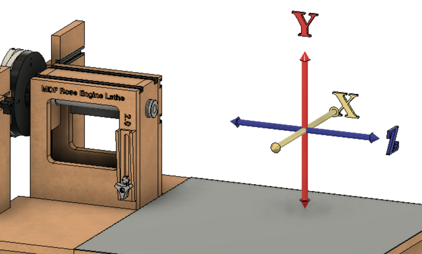
The axis identifiers are consistent with those used in machining on a lathe.
| Axis | Comments | |||||||||||||||||||||||||||||||||||||||||||||||||||||||||||||||||||||||||||||||||||||||||||||||||||||||||||||||||||||||||||||||||||||||||||||||||||||||||||||||||||||||||||||||||||||||||||||||||||||||||||||||||||||||||||||||||||||||||||||||||||||||||||||||||||||||||||||||||||||||||||||||||||||||||||||||||||||||||||||||||||||||||||||||||||||||||||||||||||||||||||||||||||||||||||||||||||||||||||||||||||||||||||||||||||||||||||||||||||||||||||||||||||||||||||||||||||||||||||||||||||||||||||||||||||||||||||||||||||||||||||||||||||||||||||||||||||||||||||||||||||||||||||||||||||||||||||||||||||||||||||||||||||||||||||||||||||||||||||||||||||||||||||||||||||||||||||||||||||||||||||||||||||||||||||||||||||||||||||||||||||||||||||||||||||||||||||||||||||||||||||||||||||||||||||||||||||||||||||||||||||||||||||||||||||||||||||||||||||||||||||||||||||||||||||||||||||||||||||||||||||||||||||||||||||||||||||||||||||||||||||||||||||||||||||||||||||||||||||||||||||||||||||||||||||||||||||||||||||||
| Traditional Cartesian Coordinate Axes | ||||||||||||||||||||||||||||||||||||||||||||||||||||||||||||||||||||||||||||||||||||||||||||||||||||||||||||||||||||||||||||||||||||||||||||||||||||||||||||||||||||||||||||||||||||||||||||||||||||||||||||||||||||||||||||||||||||||||||||||||||||||||||||||||||||||||||||||||||||||||||||||||||||||||||||||||||||||||||||||||||||||||||||||||||||||||||||||||||||||||||||||||||||||||||||||||||||||||||||||||||||||||||||||||||||||||||||||||||||||||||||||||||||||||||||||||||||||||||||||||||||||||||||||||||||||||||||||||||||||||||||||||||||||||||||||||||||||||||||||||||||||||||||||||||||||||||||||||||||||||||||||||||||||||||||||||||||||||||||||||||||||||||||||||||||||||||||||||||||||||||||||||||||||||||||||||||||||||||||||||||||||||||||||||||||||||||||||||||||||||||||||||||||||||||||||||||||||||||||||||||||||||||||||||||||||||||||||||||||||||||||||||||||||||||||||||||||||||||||||||||||||||||||||||||||||||||||||||||||||||||||||||||||||||||||||||||||||||||||||||||||||||||||||||||||||||||||||||||||||
| X |
Perpendicular to the axis of the spindle
Parallel to the plane of the lathe's bed |
The object held in the lathe is rotated 90°; thusly, the top and bottom of the piece are aligned with the spindle. | ||||||||||||||||||||||||||||||||||||||||||||||||||||||||||||||||||||||||||||||||||||||||||||||||||||||||||||||||||||||||||||||||||||||||||||||||||||||||||||||||||||||||||||||||||||||||||||||||||||||||||||||||||||||||||||||||||||||||||||||||||||||||||||||||||||||||||||||||||||||||||||||||||||||||||||||||||||||||||||||||||||||||||||||||||||||||||||||||||||||||||||||||||||||||||||||||||||||||||||||||||||||||||||||||||||||||||||||||||||||||||||||||||||||||||||||||||||||||||||||||||||||||||||||||||||||||||||||||||||||||||||||||||||||||||||||||||||||||||||||||||||||||||||||||||||||||||||||||||||||||||||||||||||||||||||||||||||||||||||||||||||||||||||||||||||||||||||||||||||||||||||||||||||||||||||||||||||||||||||||||||||||||||||||||||||||||||||||||||||||||||||||||||||||||||||||||||||||||||||||||||||||||||||||||||||||||||||||||||||||||||||||||||||||||||||||||||||||||||||||||||||||||||||||||||||||||||||||||||||||||||||||||||||||||||||||||||||||||||||||||||||||||||||||||||||||||||||||||||||
| Y |
Perpendicular to the axis of the spindle
Perpendicular to the plane of the lathe's bed |
|||||||||||||||||||||||||||||||||||||||||||||||||||||||||||||||||||||||||||||||||||||||||||||||||||||||||||||||||||||||||||||||||||||||||||||||||||||||||||||||||||||||||||||||||||||||||||||||||||||||||||||||||||||||||||||||||||||||||||||||||||||||||||||||||||||||||||||||||||||||||||||||||||||||||||||||||||||||||||||||||||||||||||||||||||||||||||||||||||||||||||||||||||||||||||||||||||||||||||||||||||||||||||||||||||||||||||||||||||||||||||||||||||||||||||||||||||||||||||||||||||||||||||||||||||||||||||||||||||||||||||||||||||||||||||||||||||||||||||||||||||||||||||||||||||||||||||||||||||||||||||||||||||||||||||||||||||||||||||||||||||||||||||||||||||||||||||||||||||||||||||||||||||||||||||||||||||||||||||||||||||||||||||||||||||||||||||||||||||||||||||||||||||||||||||||||||||||||||||||||||||||||||||||||||||||||||||||||||||||||||||||||||||||||||||||||||||||||||||||||||||||||||||||||||||||||||||||||||||||||||||||||||||||||||||||||||||||||||||||||||||||||||||||||||||||||||||||||||||||
| Z |
Parallel to the axis of the spindle
Parallel to the plane of the lathe's bed |
|||||||||||||||||||||||||||||||||||||||||||||||||||||||||||||||||||||||||||||||||||||||||||||||||||||||||||||||||||||||||||||||||||||||||||||||||||||||||||||||||||||||||||||||||||||||||||||||||||||||||||||||||||||||||||||||||||||||||||||||||||||||||||||||||||||||||||||||||||||||||||||||||||||||||||||||||||||||||||||||||||||||||||||||||||||||||||||||||||||||||||||||||||||||||||||||||||||||||||||||||||||||||||||||||||||||||||||||||||||||||||||||||||||||||||||||||||||||||||||||||||||||||||||||||||||||||||||||||||||||||||||||||||||||||||||||||||||||||||||||||||||||||||||||||||||||||||||||||||||||||||||||||||||||||||||||||||||||||||||||||||||||||||||||||||||||||||||||||||||||||||||||||||||||||||||||||||||||||||||||||||||||||||||||||||||||||||||||||||||||||||||||||||||||||||||||||||||||||||||||||||||||||||||||||||||||||||||||||||||||||||||||||||||||||||||||||||||||||||||||||||||||||||||||||||||||||||||||||||||||||||||||||||||||||||||||||||||||||||||||||||||||||||||||||||||||||||||||||||||
| Additional Axes | ||||||||||||||||||||||||||||||||||||||||||||||||||||||||||||||||||||||||||||||||||||||||||||||||||||||||||||||||||||||||||||||||||||||||||||||||||||||||||||||||||||||||||||||||||||||||||||||||||||||||||||||||||||||||||||||||||||||||||||||||||||||||||||||||||||||||||||||||||||||||||||||||||||||||||||||||||||||||||||||||||||||||||||||||||||||||||||||||||||||||||||||||||||||||||||||||||||||||||||||||||||||||||||||||||||||||||||||||||||||||||||||||||||||||||||||||||||||||||||||||||||||||||||||||||||||||||||||||||||||||||||||||||||||||||||||||||||||||||||||||||||||||||||||||||||||||||||||||||||||||||||||||||||||||||||||||||||||||||||||||||||||||||||||||||||||||||||||||||||||||||||||||||||||||||||||||||||||||||||||||||||||||||||||||||||||||||||||||||||||||||||||||||||||||||||||||||||||||||||||||||||||||||||||||||||||||||||||||||||||||||||||||||||||||||||||||||||||||||||||||||||||||||||||||||||||||||||||||||||||||||||||||||||||||||||||||||||||||||||||||||||||||||||||||||||||||||||||||||||||
| A |
Rotation about the X axis. |
This would be used if a rotary table is implemented on a dome chuck.
The M3 or M4 stepper motor could be used for driving this. |
||||||||||||||||||||||||||||||||||||||||||||||||||||||||||||||||||||||||||||||||||||||||||||||||||||||||||||||||||||||||||||||||||||||||||||||||||||||||||||||||||||||||||||||||||||||||||||||||||||||||||||||||||||||||||||||||||||||||||||||||||||||||||||||||||||||||||||||||||||||||||||||||||||||||||||||||||||||||||||||||||||||||||||||||||||||||||||||||||||||||||||||||||||||||||||||||||||||||||||||||||||||||||||||||||||||||||||||||||||||||||||||||||||||||||||||||||||||||||||||||||||||||||||||||||||||||||||||||||||||||||||||||||||||||||||||||||||||||||||||||||||||||||||||||||||||||||||||||||||||||||||||||||||||||||||||||||||||||||||||||||||||||||||||||||||||||||||||||||||||||||||||||||||||||||||||||||||||||||||||||||||||||||||||||||||||||||||||||||||||||||||||||||||||||||||||||||||||||||||||||||||||||||||||||||||||||||||||||||||||||||||||||||||||||||||||||||||||||||||||||||||||||||||||||||||||||||||||||||||||||||||||||||||||||||||||||||||||||||||||||||||||||||||||||||||||||||||||||||||
| B | Rotation about the Y axis. |
This gets used with a rotary slide.
The M3 or M4 stepper motor could be used for driving this. |
||||||||||||||||||||||||||||||||||||||||||||||||||||||||||||||||||||||||||||||||||||||||||||||||||||||||||||||||||||||||||||||||||||||||||||||||||||||||||||||||||||||||||||||||||||||||||||||||||||||||||||||||||||||||||||||||||||||||||||||||||||||||||||||||||||||||||||||||||||||||||||||||||||||||||||||||||||||||||||||||||||||||||||||||||||||||||||||||||||||||||||||||||||||||||||||||||||||||||||||||||||||||||||||||||||||||||||||||||||||||||||||||||||||||||||||||||||||||||||||||||||||||||||||||||||||||||||||||||||||||||||||||||||||||||||||||||||||||||||||||||||||||||||||||||||||||||||||||||||||||||||||||||||||||||||||||||||||||||||||||||||||||||||||||||||||||||||||||||||||||||||||||||||||||||||||||||||||||||||||||||||||||||||||||||||||||||||||||||||||||||||||||||||||||||||||||||||||||||||||||||||||||||||||||||||||||||||||||||||||||||||||||||||||||||||||||||||||||||||||||||||||||||||||||||||||||||||||||||||||||||||||||||||||||||||||||||||||||||||||||||||||||||||||||||||||||||||||||||||
| C | Rotation about the Z axis, or the Spindle. |
This gets used when turning the rosette at a different speed than the spindle, among other things.
In version 3.0, this is also used as a short descriptor for the axis controlled by the M3 stepper motor. |
||||||||||||||||||||||||||||||||||||||||||||||||||||||||||||||||||||||||||||||||||||||||||||||||||||||||||||||||||||||||||||||||||||||||||||||||||||||||||||||||||||||||||||||||||||||||||||||||||||||||||||||||||||||||||||||||||||||||||||||||||||||||||||||||||||||||||||||||||||||||||||||||||||||||||||||||||||||||||||||||||||||||||||||||||||||||||||||||||||||||||||||||||||||||||||||||||||||||||||||||||||||||||||||||||||||||||||||||||||||||||||||||||||||||||||||||||||||||||||||||||||||||||||||||||||||||||||||||||||||||||||||||||||||||||||||||||||||||||||||||||||||||||||||||||||||||||||||||||||||||||||||||||||||||||||||||||||||||||||||||||||||||||||||||||||||||||||||||||||||||||||||||||||||||||||||||||||||||||||||||||||||||||||||||||||||||||||||||||||||||||||||||||||||||||||||||||||||||||||||||||||||||||||||||||||||||||||||||||||||||||||||||||||||||||||||||||||||||||||||||||||||||||||||||||||||||||||||||||||||||||||||||||||||||||||||||||||||||||||||||||||||||||||||||||||||||||||||||||||
| Other Axes | ||||||||||||||||||||||||||||||||||||||||||||||||||||||||||||||||||||||||||||||||||||||||||||||||||||||||||||||||||||||||||||||||||||||||||||||||||||||||||||||||||||||||||||||||||||||||||||||||||||||||||||||||||||||||||||||||||||||||||||||||||||||||||||||||||||||||||||||||||||||||||||||||||||||||||||||||||||||||||||||||||||||||||||||||||||||||||||||||||||||||||||||||||||||||||||||||||||||||||||||||||||||||||||||||||||||||||||||||||||||||||||||||||||||||||||||||||||||||||||||||||||||||||||||||||||||||||||||||||||||||||||||||||||||||||||||||||||||||||||||||||||||||||||||||||||||||||||||||||||||||||||||||||||||||||||||||||||||||||||||||||||||||||||||||||||||||||||||||||||||||||||||||||||||||||||||||||||||||||||||||||||||||||||||||||||||||||||||||||||||||||||||||||||||||||||||||||||||||||||||||||||||||||||||||||||||||||||||||||||||||||||||||||||||||||||||||||||||||||||||||||||||||||||||||||||||||||||||||||||||||||||||||||||||||||||||||||||||||||||||||||||||||||||||||||||||||||||||||||||||
| D | Not truly an axis per se | In version 3.0, this is used as a short descriptor for the axis controlled by the M4 stepper motor. | ||||||||||||||||||||||||||||||||||||||||||||||||||||||||||||||||||||||||||||||||||||||||||||||||||||||||||||||||||||||||||||||||||||||||||||||||||||||||||||||||||||||||||||||||||||||||||||||||||||||||||||||||||||||||||||||||||||||||||||||||||||||||||||||||||||||||||||||||||||||||||||||||||||||||||||||||||||||||||||||||||||||||||||||||||||||||||||||||||||||||||||||||||||||||||||||||||||||||||||||||||||||||||||||||||||||||||||||||||||||||||||||||||||||||||||||||||||||||||||||||||||||||||||||||||||||||||||||||||||||||||||||||||||||||||||||||||||||||||||||||||||||||||||||||||||||||||||||||||||||||||||||||||||||||||||||||||||||||||||||||||||||||||||||||||||||||||||||||||||||||||||||||||||||||||||||||||||||||||||||||||||||||||||||||||||||||||||||||||||||||||||||||||||||||||||||||||||||||||||||||||||||||||||||||||||||||||||||||||||||||||||||||||||||||||||||||||||||||||||||||||||||||||||||||||||||||||||||||||||||||||||||||||||||||||||||||||||||||||||||||||||||||||||||||||||||||||||||||||||
File Formatting
In all cases, the # symbol below is used as a multiplier or actual length.
General Purpose
| Axis | Identifier | Identifier Usage | Syntax Notes | Comments |
| n/a | ; | Comment |
|
There is no limit on the number of comment lines in a file. |
| n/a | E | End of the instructions |
|
All files must have this as the last line in the file. |
| n/a | P# | Pause in seconds. |
|
This is often used to allow time for manually moving the cutter in or out. |
Segment Counts
| Axis | Identifier | Identifier Usage | Syntax Notes | Comments |
| n/a | WA# | Set the axial size of the pattern. |
|
This identifier is required for all patterns. Prior to v21, this was A#. |
| Sp | WS# | Set the radial size of the pattern. |
|
This identifier is required for all patterns. Prior to v21, this was S#. |
| M3 | WB# | Sets how many M3 radial segments in the file. |
|
When M3 is driving a rotary table holding the workpiece and it is set to Radial on the motor page, WB should be used to set the segment length, similar to WS for the spindle. When M3 is driving a rotary table holding a sliderest (spherical apparatus), WB should not be used. WD should also not be used when M4 is set to Linear. |
| M4 | WD# | Sets how many M4 radial segments in the file. |
|
When M4 is driving a rotary table holding the workpiece and it is set to Radial on the motor page, WD should be used to set the segment length, similar to WS for the spindle. When M4 is driving a rotary table holding a sliderest (spherical apparatus), WD should not be used. WD should also not be used when M4 is set to Linear. |
Spindle Moves
| Axis | Identifier | Identifier Usage | Syntax Notes | Comments |
| Sp |
S#
S-# |
Rotate the spindle. |
Prior to v21, this was U# or D#.
|
|
| C |
C#
C-# |
Move about the C axis. |
|
The C axis is the same as the spindle; i.e., a rotation about the Z axis. |
Enable or Disable Stepper Motors
| Axis | Identifier | Identifier Usage | Syntax Notes | Comments |
| Sp | KS# | Enable / disable the spindle. |
|
Steppers are automatically enabled when executing a command, so it is not necessary to enable one after disabling it. |
| X | KX# | Enable / disable the X Axis. | ||
| Z | KZ# | Enable / disable the Z Axis. | ||
| M3 | KB# | Enable / disable the M3 Axis. | ||
| n/a | KA# | Enable / disable the current Program Page Axis. |
Axis Moves
Based on Sync Screen Selection
| Axis | Identifier | Identifier Usage | Syntax Notes | Comments | ||||||||
| n/a |
A#
A-# |
Move the cutter along the axis selected on the Grk screen. |
|
I and O are opposite moves from each other. Think of them as "In" or "Out". They are used to move the cutter into or away from the workpiece to allow for moving to a new position without cutting. Prior to v21, A# was R# or L#. |
||||||||
| n/a | I# |
Move the cutter into the workpiece.
This is movement along the opposite axis from what was selected on the Program screen. |
|
|||||||||
| n/a | O# |
Move the cutter out from (away from) the workpiece.
This is movement along the opposite axis from what was selected on the Program screen. |
|
Axis Moves
Hardcoded Axis Selection
| Axis | Identifier | Identifier Usage | Syntax Notes | Comments | |||||
| X |
X#
X-# |
Move the cutter along the X axis. |
|
These hardcoded axis selections are used to move the cutter along the identified axis, regardless of what is selected on the Grk screen
|
|||||
| Z |
Z#
Z-# |
Move the cutter along the Z axis. |
|
||||||
|
M3
or B |
B#
B-# |
Move the cutter along the M3 axis. |
|
||||||
| M4 |
D#
D-# |
Move the cutter along the M4 axis. |
|
Coordinated Axis & Spindle Moves
| Axis | Identifier | Identifier Usage | Syntax Notes | Comments | ||||||||||||
| n/a |
H#
H-# V# V-# |
Specifies a coordinated move with the spindle and the active axis. |
|
|
||||||||||||
| n/a | Ta1#a2# | Specifies a coordinated move between two axes. |
|
This allows Cartesian movements when the M3 or M4 are set to Linear, and Polar movements when they are set to Radial. This works similar to the HV command except you can specify which two axes(motors) you want to move. |
Page Call: Index Page
These were introduced in v23. If your system is a prior version, they will not work.
| Axis | Identifier | Identifier Usage | Syntax Notes | Comments | ||||||
| Sp | NN# | Index the spindle using settings on the Index page, using settings on that page. |
|
Settings on the page are used. |
||||||
| NT# | Indexing approach: divisions of a circle or degrees. |
|
||||||||
| NJ# | Index ID |
|
Page Call: Move Page
These were introduced in v23. If your system is a prior version, they will not work.
| Axis | Identifier | Identifier Usage | Syntax Notes | Comments | ||||||
| n/a | FF# | Moves an axis using settings on the Move page, using settings on that page. |
|
Settings on the page are used. Axes should be set the same on the Program page as they are on the called page. I and O will usually be used in conjunction with the page moves. They take the axis setting on the Program page and the page moves use the settings on that page. |
||||||
| n/a | FD# | Move Distance |
|
Page Call: MultiSync Page
These were introduced in v3.1.3. If your system is a prior version, they will not work.
| Axis | Identifier | Identifier Usage | Syntax Notes | Comments | ||||
| n/a | Execute the moves specified on the MultiSync page, using settings on that page. |
Settings on the page are used. Axes should be set the same on the Program page as they are on the called page. I and O will usually be used in conjunction with the page moves. They take the axis setting on the Program page and the page moves use the settings on that page. |
||||||
| X | QA | X target (floating point) | ||||||
| QB | X waves (floating point) | |||||||
| QC | X direction |
|
||||||
| QD | X checked |
|
||||||
| Z | QE | Z target (floating point) | ||||||
| QF | Z waves (floating point) | |||||||
| QG | Z direction |
|
||||||
| QH | Z checked |
|
||||||
| M3 | QI | M3 target (floating point) | ||||||
| QJ | M3 waves (floating point) | |||||||
| QK | M3 direction |
|
||||||
| QL | M3 checked |
|
||||||
| M4 | QM | M4 target (floating point) | ||||||
| QN | M4 waves (floating point) | |||||||
| QO | M4 direction |
|
||||||
| QP | M4 checked |
|
||||||
| Sp | QS | Spindle target (floating point) | ||||||
| QT | Spindle waves (floating point) | |||||||
| QU | Spindle direction |
|
||||||
| QV | Spindle checked |
|
Page Call: Recip Page
These were introduced in v23. If your system is a prior version, they will not work.
| Axis | Identifier | Identifier Usage | Syntax Notes | Comments | ||||||
| n/a | VV# | Execute the moves specified on the Recip page, using settings on that page. |
|
Settings on the page are used. Axes should be set the same on the Program page as they are on the called page. I and O will usually be used in conjunction with the page moves. They take the axis setting on the Program page and the page moves use the settings on that page. |
||||||
| n/a | VT# | Reciprocation type. |
|
|||||||
| n/a | VK# | Reciprocation style |
|
|||||||
| n/a | VW# | Reciprocation Waves |
|
|||||||
| n/a | VS# | Reciprocation Spindle |
|
|||||||
| n/a | VA# | Reciprocation Axis |
|
Page Call: Rose Page
These were introduced in v3.1.3. If your system is a prior version, they will not work.
| Axis | Identifier | Identifier Usage | Syntax Notes | Comments | ||||||
| n/a | RR# | Execute the moves specified on the Rose page, using settings on that page. |
|
Settings on the page are used. Axes should be set the same on the Program page as they are on the called page. I and O will usually be used in conjunction with the page moves. They take the axis setting on the Program page and the page moves use the settings on that page. |
||||||
| n/a | RN | Set n (floating point) | ||||||||
| n/a | RD | Set d (floating point) | ||||||||
| n/a | RS | Set spindle revolutions (floating point) | ||||||||
| n/a | RA | Set axis distance (floating point) |
Page Call: Sync Page
These were introduced in v23. If your system is a prior version, they will not work.
| Axis | Identifier | Identifier Usage | Syntax Notes | Comments | ||||||
| n/a | GG# | Execute the moves specified on the Sync page, using settings on that page. |
|
Settings on the page are used. Axes should be set the same on the Program page as they are on the called page. I and O will usually be used in conjunction with the page moves. They take the axis setting on the Program page and the page moves use the settings on that page. |
||||||
| n/a | GH# | Helix type |
|
|||||||
| n/a | GD# | Distance |
|
|||||||
| n/a | GR# | Revolutions |
|
Page Call: M3 & M4 Parms
These were introduced in v3. If your system is a prior version, they will not work.
| Axis | Identifier | Identifier Usage | Syntax Notes | Comments |
| M3 | JR# | Set the value for the M3 radius. |
|
If using a version prior to 3.0, this is for the B axis. |
| M4 | LR# | Set the value for the M4 radius. |
|
|
The example file below ...
|
... produces the movements seen below.  |
|
These file identifiers were deprecated in version 3.0, and are no longer supported. They are listed here for historical purposes, and to assist in converting to the newer 3.0 identifiers.
| Identifier | Identifier Usage | Syntax Notes | Comments |
| NI# | Number of divisions or degrees for each index |
|
Recommend upgrading to V3.0, and using the other Nx identifiers. |
| QI# | Executed the move specified on the Index page. |
|
Recommend upgrading to V3.0, and using the Nx identifiers. |
| QM# | Execute the move specified on the Move page. |
|
Recommend upgrading to V3.0, and using the Fx identifiers. |
| QR# | Execute the move specified on the Recip> page. |
|
Recommend upgrading to V3.0, and using the Vx identifiers. |
|
QS#
QS-# |
Execute the moves specified on the Sync page. |
|
Recommend upgrading to V3.0, and using the Gx identifiers. |
|
Questions or comments? Contact us at
ColvinTools@Gmail.com |
Disclaimers |