|
|
Indicates that the selected stepper motor is enabled even when not in use. Touch this to change it to Disabled.
|
The More screen can be used to set this to be continuously Disabled or Enabled. These buttons temporarily override that configuration setting.
Key Note:When using DM542T stepper motor drivers, this needs to be Enabled (especially for work using indexing), otherwise the position will be lost and the movement will not be predictable.
|
|
|
|
Indicates that the selected stepper motor is only enabled when in use, and then disabled. Touch this to change it to Enabled.
|

|
Used to turn the spindle counter-clockwise. On a traditional lathe, this is considered forward.
|

|
Used to turn the spindle clockwise. On a traditional lathe, this is considered reverse. To change the direction of the spindle, you must stop it first. You cannot directly swap between clockwise and counter-clockwise.
|

|
Used to stop the motion of the stepper motor.
|
|
Used to return the spindle or the selected axis to the start point of the previous operation.
When using this function, Be sure to stop and retract the cutter from the cut first. The return path does not always follow the same path as the initial cut. (Backlash and other factors come into play here.)
The speed of the return action is set in the Preferences | Returns screen.
|

|
Used to move the item on the respective axis (e.g., a cutting frame) in the negative direction. If this is the Z axis, that is to the left; for the X, it is towards the back of the lathe.
Note: This will display as shown if the M3 or M4 axis is selected, and that axis is set to radial (vs. linear).
|

|
Used to move the item on the respective axis (e.g., a cutting frame) in the positive direction. If this is the Z axis, that is to the right; for the X, it is towards the front of the lathe.
Note: This will display as shown if the M3 or M4 axis is selected, and that axis is set to radial (vs. linear).
|
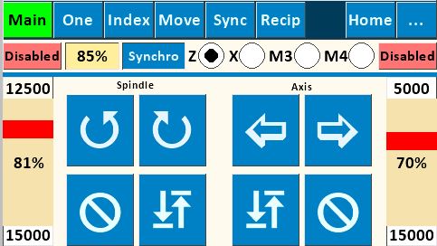
Purpose: This screen allows for direct control of
- the spindle's speed and direction, and
- the axis speed and direction for one other, independent stepper motor.
This screen is typically used for continuous spindle and/or continuous axis motion (turning or facing cuts, continuous rose engine patterns on cylindrical or face surfaces, etc.).
|
|
|
|
|

Sync %
|
This option is used to run the spindle and M3 stepper motors synchronously at the specified percentages. Negative numbers run the spindle and M3 in opposite directions.
This option only works if the Synchro function button is enabled (not red).
This function is useful for activities such as having the spindle and the rosette(s) run at different revolutions per minute (i.e., a second stepper motor is driving the rosette's rotation).
|
|
|
Speed
|
The controls on the left and right side of the screen are for controlling the respective stepper motor's speed and acceleration.
To change the Max Speed, touch the number, and you will be presented with the Number Pad Screen.
The slider is a red bar that can be moved up to increase the speed, or down to decrease it.
Want to understand this better? More details about the stepper motor speeds are on this page.
|
|
|
|
Acceleration
|
The bottom number (1024 on the left; 500 on the right) is the acceleration for the stepper motor.
To change this value, touch the number, and you will be presented with the Number Pad Screen.
|
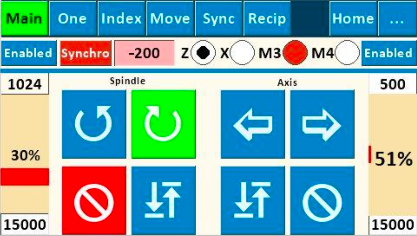
M3 and M4 Axes
If the M3 or M4 is set to be linear movement, the screen will show as below.
Limit Switches & EStop
Limit switches can be used with this function. The pins used for this are configured on the Limit Switches Configuration Screen. (More information about the implementation of limit switches is on that page.)
If the EStop is engaged when using this function, all the movement buttons will turn red.
To reset:
- Ensure the EStop switch is not closed, and
- Touch one of the stop buttons.
|


