|
Touch the buttons on the screen image to the right to see the details for the that screen.
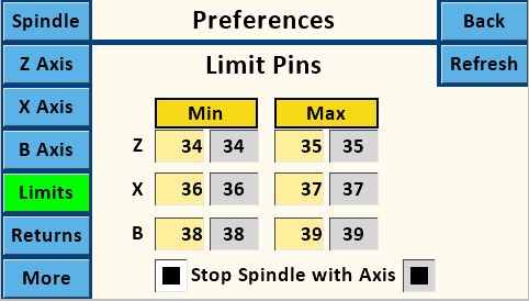
Purpose: Set pin numbers to be used for limit switches.
The use of a specific pin (Min or Max) for a given axis is not critical. Tripping either of the limit switches stops movement.
The MDF Rose Engine Lathe 2.0 design has jacks connected to pins 34 thru 39. (The Teensy microcontroller does allow for pins 25 thru 39 are available to be used, but these are not in the MDF Rose Engine Lathe 2.0 design.)
Limit switches can be used with the Main Screen or One Screen. The other screens do not accommodate use of limit switches.
- The values shown in a tan box show values on the Nextion. Touching one of the text boxes allows you to edit that value using the Number Pad screen.
- The values shown in a gray box show the ones stored on the Teensy controller. These are read only and should match the settings on the Nextion.

|
Min pin is used when moving in the direction towards the headstock
|
|
|
|
Max pin is used when moving in the direction away from the headstock
|

|
|
 Stop Spindle with Axis
|
This option determines what happens when the limit is triggered.
= Stop motion on both the axis (i.e., Z, X, or B) and the spindle when the limit is triggered.
 = Stop motion on the axis only when the limit is triggered (the spindle remains turning). = Stop motion on the axis only when the limit is triggered (the spindle remains turning).
|
Using Limit Switches: The limit switches are implemented using a switch which is
normally open / momentary close
Connecting any of the designated pins to ground triggers the limit.
|
|
Version
|
How It Works
|
|
Prior to 17
|
When the limit is triggered, the system stops.
To restart after a stop, power down the system, and then power it back up.
The system is setup this way to prevent damage to the machinery if it left unattended for a while.
|
|
17+
|
When the limit is triggered, the system stops.
To reset after a stop, touch the stop button (shown to the right). You will have to do this for both the spindle and the axis in use.
The system is setup this way to prevent damage to the machinery if it left unattended for a while, but also to allow the artist to get to the next operation quicker.
|
|
 3.5 mm Plug
The 3.5 mm (1/8") jack used on the MDF Rose Engine Lathe 2.0 has the plug's tip connected to the respective pin on the Teensy, and the sleeve is connected to ground. Shorting across these two will cause the limit condition to trigger.
Using the sleeve for the ground is key for many reasons, and that is the design outlined in Instructions for Building the Stepper Controls.
|
 Limit Switch
With the MDF Rose Engine Lathe 2.0, we have tested using the Miniature Snap-Acting Switch with a Lever Actuator, from McMaster-Carr, p/n 7779K13.
This can be attached to a magnetic base stand, especially one with a Noga arm, to position it where needed.
|
Diagnostics: If you are experiencing issues using limit switches, below are some diagnostic steps I've found useful.
|
Limit Switches don't stop spindle movement
|
Ensure the option on this screen, "Stop Spindle with Axis", is enabled.
Recommended Action: Unless you need to not stop the spindle, leave this option checked as the default for how you use your machine.
|
|
Limit Switches don't stop axis movement
|
Ensure you are using the correct limit switch pins for the respective axis.
Recommended Action: If you are only going to use one limit switch, set all of these to 34.
If you are going to use two limit switches, set all the Mins 34 and all the Maxes to 35.
|
|
Stepper Motors won't run on Main or One Screens
|
One or more limit switches may be "engaged". This can happen if they are not wired correctly or there is a short in the limit switch wiring.
You can confirm that this is or is not the case by trying to drive the stepper motor motion from the screens which don't use limit switches. Recommended screens are the Ind, Mov, or Sync.
Recommended Action: Read the instructions regarding limit switch connections in Instructions for Building the Stepper Controls.
|
|