ELFOS

Dynamic Rosette Phasing & Lobe Multiplication
using the
Rosette Phaser / Multiplier


Calculations needed for dynamic phasing when using the Rosette Phaser / Multiplier are based on the data in the table below. Input fields on this screen are  colored yellow .

Once you have entered your desired values, scroll down and click the button below,  Calculate MultiSync Values 

Data Input

Rosette Multiplication

Actual Rosette Lobes Number of lobes on the rosette
Desired Rosette Lobes

Lobes desired

Rosette Phasing

Z Axis Target Distance travelled along the Z axis.
Z Axis Stepover per Revolution

Distance moved along the Z axis per revolution of the spindle. For the desired surface finish, use these values:

  • Rough > 0.10"
  • Very Fine <= 0.02"
Rosette Pattern Rotation ° Amount of revolution of the rosette's pattern across the Z distance.
Final Average Diameter Diameter of the object at the middle of the cutting. This is used to calculate the rotation of the UCF. If using this on a curvilinear slide, it is the average diameter of the piece.
Rosette Pattern's Direction of Rotation
This is the direction of the rotation of the rosette's pattern around the spindle axis. A right (handed) helix is like a standard screw.
Z Axis Direction
This is the direction of movement along the Z axis.
 
MultiSync Page Data UCF Rotation
Run Single Dir Target Max Speed %
Z

5000 100
X        
M3

15000 100
M4        
Spindle


°
 

As seen from the operator side


Usage Notes

  1. The system will run at the slowest selected speed. Therefore, these settings are at the max for Z and M3, allowing the speed settings for the Spindle to control all 3.

  2. There are other means for achieving such rotation; however this is presented as one for helping you achieve your goals. As you grow your skills, you will find other approaches may be better. The overarching ideas with this approach are:

    1. The Z axis direction sets the direction of cut.

    2. There is a relationship between the M3° and the Spindle°:
      1. M3° < Spindle° = pattern rotates in a right helix
      2. M3° > Spindle° = pattern rotates in a left helix

    3. The direction of pattern rotation sets the direction of UCF rotation. This does not change based on the direction of movement on the Z axis.
      1. A right helical pattern rotation requires the UCF to be rotated clockwise (when observed from the operator side).
      2. A left helical pattern rotation requires the UCF to be rotated counter clockwise (when observed from the operator side).

      You should ensure the UCF is rotated the correct direction for the direction of the rosette's pattern rotation. When rotated correctly, there is a smooth line for the root of the helix. A light cut on the first pass can help assure proper direction of rotation.

    4. You must ensure the Spindle and M3 axes are rotating the same direction
    5. Correct
       
      Incorrect
      Spindle M3
      or
      Spindle M3
       
      Spindle M3
      or
      Spindle M3

Equations Used for Calculations

\begin{align*} \tag{1} Lobe \, Multiplier &= \frac {Lobes \, Desired} {Lobes \, on \, Rosette} \\ \tag{2} Spindle \, Target\unicode{xB0} &= \left(\frac {Z \, Axis \, Target} {Z \, Axis \, Stepover \, per \, Revolution} \right) \cdot 360\unicode{xB0} \\ \tag{3} M3 \, Target \unicode{xB0} &= \left(Spindle \, Target\unicode{xB0} + Rosette \, Pattern \, Rotation\unicode{xB0}\right) \cdot Lobe \, Multiplier \\ \end{align*}

Note, when making a left helix, the Rosette Pattern Rotation will be a negative number.


UCF Rotation Calculation

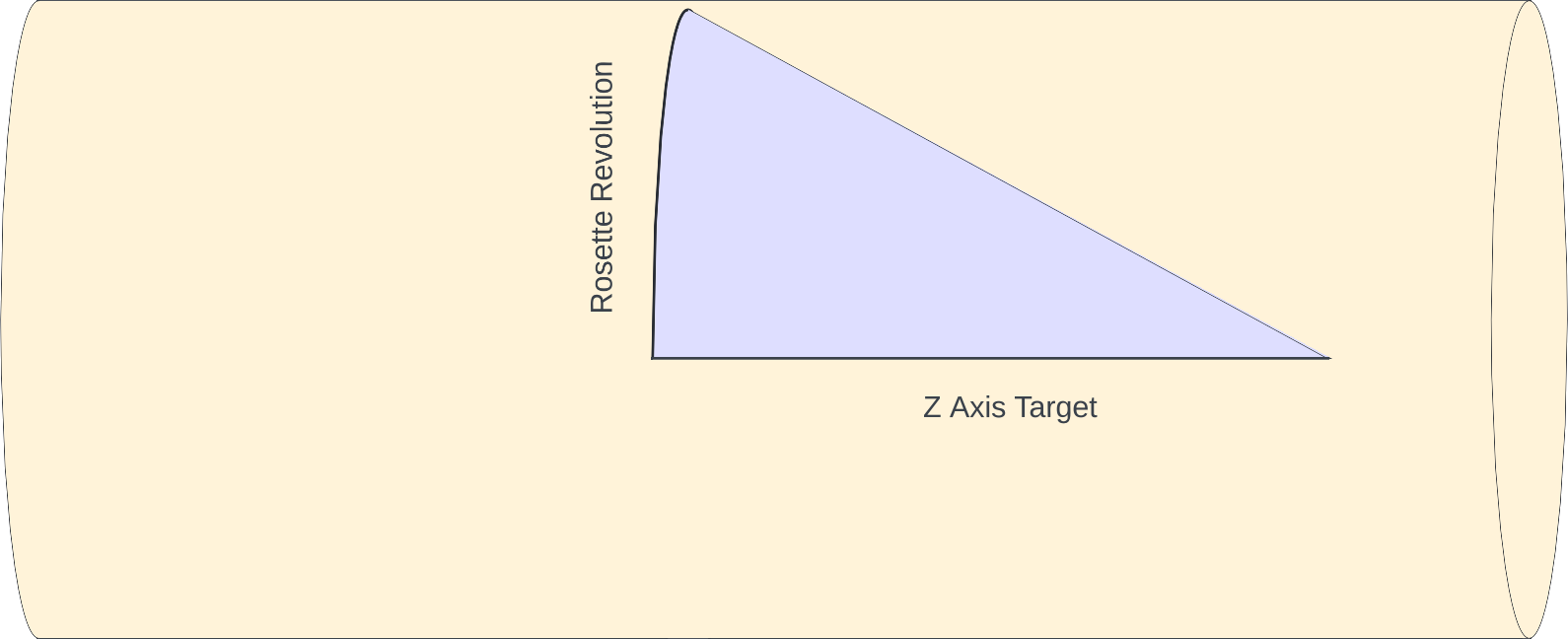
Triangle Wrapped Around a Cylinder

For the angle to set the universal cutting frame (UCF), imagine there is a triangle where the adjacent side is along the Z axis, and the opposite side is wrapped around the face, perpendicular to the Z axis. The image to the right shows such a triangle.

Opposite Side of the Triangle

The cylinder's circumference at the Final Average Diameter is π times that. A rosette's revolution, specified in degrees (°), would of course be that portion of the cylinder's circumference. Thus, the Rosette Pattern Rotation distance is calculated as a fraction of the cylinder circumference. \begin{align*} \tag{4} Cylinder \, circumference &= \pi \cdot Final \, Average \, Diameter \\ \tag{5} Rosette \, Pattern \, Revolution \, Distance &= Cylinder \, circumference \cdot \left(\frac {Rosette \, Pattern \, Revolution\unicode{xB0}} {360\unicode{xB0}} \right) \end{align*}

Adjacent Side of the Triangle

For the adjacent side, we use the Z Axis Target.

Calculation of the UCF Rotation Angle

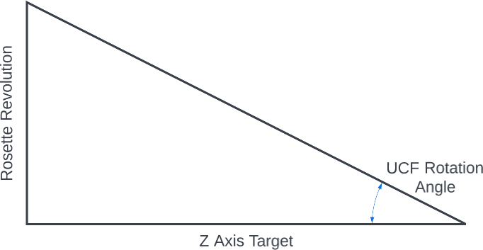
Angle to be Calculated

The UCF Rotation Angle is then calculated using the tan-1 (arctan) calculation. \begin{align*} \tag{6} UCF \, Rotation \unicode{xB0} &= \tan^{-1} \left(\frac {Rosette \, Revolution \, Distance} {Z \, Axis \, Target} \right) \end{align*}


Questions or comments? Contact us at
ColvinTools@Gmail.com
Disclaimers