The factors on these screens control how speeds and distances are determined.
|
|
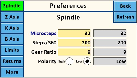
Microsteps
|
This must use valid values for the stepper driver, and is usually 1, 2, 4, 16, 32, 64, or 128. These settings must match the jumper settings on the PCB.
32 is the designed value for the MDF Rose Engine Lathe 2.0 (as outlined in Instructions for Building the Stepper Controls).
|
|
|
|
Steps/360
|
This must use valid values for the stepper motor. The typical step angle is 1.8 deg, so this would be
\[
\frac{360 \, \mathrm{deg}}{1.8 \, \mathrm{deg}} = 200
\]
200 is the designed value for the MDF Rose Engine Lathe 2.0 (as outlined in Instructions for Building the Stepper Controls).
|
|
|
|
Gear Ratio
|
This is the ratio of the gear on the stepper motor to the gear driving the spindle. This value drives the calculation of RPM.
9 is the designed value for the MDF Rose Engine Lathe 2.0 (as outlined in Instructions for Building the Stepper Controls).
|
|
|
Polarity
|
The Polarity High and Low radio buttons for both Spindle and Z Axis are set as:
|
High
|

|
High setting is for use for some external stepper drivers
|
|
Low
|

|
Low is the default, which is the correct setting when using the StepperOnline DM542T and the Pololu DRV8825 Stepper Drivers.
|
|